
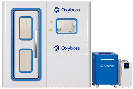
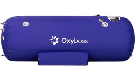
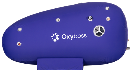
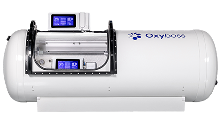
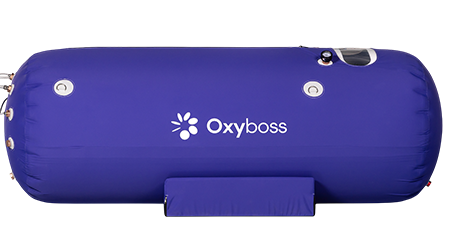
A home hyperbaric chamber project is not a raw-vessel fabrication project. It is a site-planning and system-integration project built around a pressure-rated chamber. The shell, the door geometry, the viewport stack, the penetrations, the relief path, the structural welds — those sit on the factory side. They do not move into a garage because the install address changed.
That line matters. Everything after that gets clearer.
Start With the Pressure Boundary
We treat the pressure boundary as untouchable during home assembly.
Not “mostly fixed.” Not “fine unless you know what you are doing.” Untouchable.
That includes:
- chamber body
- door and latch system
- viewport assembly
- welded ports and penetrations
- pressure relief hardware
- structural fastener pattern
- calibrated pressure instruments tied to vessel safety
Once a part carries load, seals load, or protects against overpressure, it is no longer a convenience item. It becomes a risk item. People miss that. They group shell parts and accessories together because both arrive in the same crate. Bad habit.
Room Planning Before Delivery
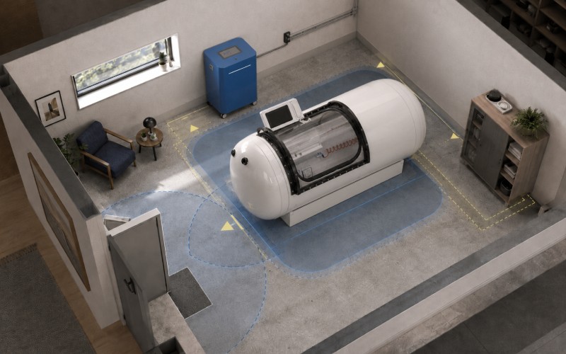
The room decides half the outcome.
Not the marketing photo. The room.
Floor and Load Path
The installed load is never just the vessel weight. Add support frame, occupants, accessories, utility lines, service clearance, and the usual creep of nearby storage. The floor needs to support the real operating footprint, not the empty-shell number.
Access and Clearance
Leave room for the door swing, side access, rear service access, panel removal, and inspection points. A chamber pushed tight against the wall may look clean on day one. By month three, it becomes a maintenance penalty.
Utility Separation
Do not bundle everything into one neat corner. Power, controls, intake, exhaust, and any gas-routing hardware should be physically organized. Not because it looks tidy. Because fault tracing gets ugly when heat, vibration, abrasion, and leak points are stacked together.
Ventilation
The room still matters even when the chamber is sealed. If your setup uses dedicated breathing support or separate internal gas routing, room ventilation stops being a background issue. It becomes part of the installation logic.
The Parts We Allow on the Home Side
| Component | Home Assembly Status | Factory Position |
| Pressure shell | No | Factory-built and factory-tested only |
| Door, hinge, latch assembly | No | Pre-engineered as part of the chamber |
| Viewport stack | No | Load-bearing transparent assembly stays factory-controlled |
| Base frame or cradle | Yes, if non-structural | Must not alter shell loads |
| External control console | Yes | Use designed connectors and approved cable paths |
| Interior cushion or support pieces | Yes | Only if they do not affect sealing, airflow, or inspection access |
| External lighting or accessories | Yes | Keep them outside the pressure wall unless the design already includes them |
| Utility routing in room | Yes | Part of the home installation scope |
| New shell holes or added ports | No | This is redesign, not assembly |
| Relief valve substitution or reset | No | Safety setpoints do not belong to field improvisation |
That table usually settles the argument fast.
Assembly Sequence We Actually Use
No drama here. Just order.
1. Delivery Inspection
Before placement, inspect the chamber as a chamber. Not as a shipment.
Check:
- shell surface condition
- transport marks near latches and flanges
- viewport condition
- connector labels
- pressure instrument protection
- seal surfaces
- serial and configuration match
A unit can arrive looking “fine” and still be wrong where it counts.
2. Base Positioning
Level the base before final alignment. A base that is slightly off creates door-load issues later. Then seal wear. Then latch inconsistency. Small placement errors do not stay small for long.
3. Utility Routing
Run intake, exhaust, power, and control lines through the intended paths only. No sharp-bend shortcuts. No improvised pass-through. No unsupported hose span that starts rubbing after two weeks.
This is where home installs quietly improve or quietly fall apart.
4. External Subsystem Connection
Connect only the approved subsystems. If the chamber was designed for an external console, dedicated air supply, control harness, or breathing support line, use those interfaces exactly as intended.
The field is not the place to “upgrade” fittings.
5. Interior Setup
Install cushions, supports, non-structural trim, and user-side accessories only after the chamber and utilities are stable. Interior additions should never block inspection points, interfere with the door path, or sit against sensitive surfaces.
6. Control Verification
Before any pressure cycle, verify the truthfulness of the controls.
Not just “does it power on.” Does it read honestly. Does the displayed condition match the physical condition. If a sensor drifts and the screen still looks calm, that is worse than a dead display.
Pressure, Temperature, and Why Small Errors Stack
Pressure systems do not fail only at the big moments. They wear at the ordinary ones.
Every cycle loads the shell. Then unloads it. The shell moves a little. Seals compress. Then relax. Transparent parts take load differently from metal. Ports behave differently from smooth wall sections. Corners, transitions, and attachments always deserve suspicion.
That is why we do not treat repeated operation like one long event. It is many short events. Repeated.
And pressure stability during hold is not as simple as “steady means good, drift means leak.” Compression heats the internal air mass. Then the system cools toward room condition. Pressure can drift during that thermal settling period without a leak being present. Good operators know the difference. Good systems account for it.
Controls Are Important. Mechanical Protection Is Final.
We like controls. We do not trust them with the last word.
A proper home-installed chamber needs a control layer and a mechanical protection layer. The control layer manages normal operation. The mechanical layer exists for the day normal operation stops being normal.
That means:
- clear pressure indication
- independent overpressure protection
- predictable shutdown behavior
- fail-safe valve logic
- physical relief path that cannot be casually blocked
Digital logic manages sequencing. Mechanical protection manages consequences.
Different job.
Gas Handling Is Where Casual Thinking Ends
This part gets sloppy online. It should not.
If a configuration uses separate breathing support, dedicated masks, or internal gas routing, then gas handling is part of the safety architecture, not a comfort feature. Cabin atmosphere, exhaust path, room ventilation, material selection, and electrical discipline all start interacting.
A common mistake is focusing on supply and ignoring exhaust. Another is treating exhaust as a convenience pipe. It is not. If the discharge path is wrong, room conditions change. If room conditions change, the whole installation changes with them.
Keep the logic simple:
- clean supply path
- controlled exhaust path
- clear separation between system functions
- no improvised fittings
- no material substitutions without review
Electrical Routing: Keep the Energy Outside When Possible
We keep higher-risk electrical loads outside the pressure boundary whenever the design allows it.
Inside the chamber, simplicity wins:
- low-voltage circuits only where needed
- sealed pass-throughs
- stable connector retention
- no loose cable loops
- no abrasion points at penetrations
A messy wire path usually signals a messy install everywhere else too.

Commissioning: The Part That Decides Whether This Is Equipment or a Project
A lot of builds look finished before they are usable.
Commissioning is what separates the two.
Our preferred sequence is staged:
Visual Review
Inspect shell-adjacent hardware, sealing surfaces, cable routing, hose support, latch behavior, gauge faces, and relief-device installation.
Functional Review
Verify controls, alarm logic, indicators, and manual overrides. Every button, every state change, every obvious fault condition.
Low-Level System Check
Confirm intended flow direction, valve behavior, and stable readings under non-operating conditions. No guessing. No “probably okay.”
Controlled Operational Validation
Move upward in measured stages. Watch instrument agreement, mechanical response, thermal behavior, noise, vibration, and repeatability.
Documentation
If a part was changed, record it. If a setting was touched, record it. If a recurring observation appears, record it. Good installations create records. Weak installations create memories. Memories are useless when the same issue comes back six weeks later.
Common Build Errors We See
Treating Structural Parts Like Accessories
A port, window, relief valve, or door component is not “just hardware.” These are boundary parts.
Chasing Neatness Over Serviceability
The prettiest install is often the one nobody can inspect.
Mixing Fittings and Materials Without System Thinking
A connection that physically fits is not automatically acceptable under pressure cycling and repeated use.
Letting the Controls Create False Confidence
A polished interface can hide a bad install. Clean screens do not prove clean mechanics.
Ignoring Repeat Behavior
A system that works once is not validated. A system that behaves the same way over repeated cycles starts to earn trust.
A Practical Pre-Use Checklist
| Check Item | What We Look For | Stop Condition |
| Door and latch movement | Smooth travel, consistent engagement, no uneven resistance | Binding, shifted alignment, inconsistent lock feel |
| Seal surfaces | Clean, continuous, undamaged contact surfaces | Cuts, flattening, debris, uneven seating |
| Pressure indication | Stable zero reference, consistent response across instruments | Gauge disagreement or unstable baseline |
| Utility routing | No sharp bends, rub points, unsupported sections | Hose abrasion, cable pinch, loose retention |
| Relief path | Clear, accessible, not obstructed or altered | Any blockage, added valve, or undocumented change |
| Room condition | Adequate clearance, ventilation, no clutter around service zones | Restricted access or poor airflow |
| Controls and alarms | Expected state changes and visible feedback | Missing response, delayed response, false readout |
Maintenance Starts on Day One
Do not wait for the first obvious fault.
The first month tells you plenty. Watch for:
- gradual pressure-hold changes
- latch feel that starts shifting
- repeated moisture pattern changes
- vibration where there used to be none
- hose wear near supports
- gauge disagreement, even slight
- operator workarounds becoming routine
The moment a workaround becomes normal, the install has started drifting away from design intent.
That is the signal. Not the failure.
FAQ
Can I fabricate the chamber body myself and install it at home?
We do not recommend that route. Home installation and raw pressure-vessel fabrication are different jobs. The shell, door, viewport stack, and relief architecture should arrive as engineered hardware, not as a field-made project.
Can I add one extra penetration for wiring or an accessory?
No. Any added shell penetration changes loading, sealing, and the original design basis. That is not a convenience edit.
Why does pressure drift during a hold even when there is no visible leak?
Because the internal air mass settles thermally after compression. A pressure change during that stabilization period does not automatically mean leakage. The pattern matters more than the first number drop.
Are digital controls enough for safety?
No. Controls are there for operation. Mechanical protection is there for fault conditions. Both are required. One cannot replace the other.
Can I swap fittings or valves with similar-looking parts from another system?
No. Visual similarity is irrelevant. Pressure cycling, sealing behavior, material compatibility, and fail-state logic all matter.
What is the biggest mistake in home chamber assembly?
Confusing installation with redesign. Once you alter the pressure boundary, relief path, or structural hardware, you are no longer assembling. You are re-engineering.
What should stay in the service log?
Configuration records, installed components, inspections, recurring observations, replaced parts, control changes, and any deviation from the original install condition.
Final Word
The safest home hyperbaric chamber build does not begin with metalwork.
It begins with restraint.
Use a real chamber. Prepare the room properly. Route utilities cleanly. Keep structural boundaries closed. Verify controls, but respect mechanical protection more. Document everything. And do not let a home install turn into a pressure-vessel experiment halfway through the job.
That is the version that stays usable.
That is the version we stand behind.